1 Introduction
The purpose of this document is to outline the Wi-Fi infrastructure high-level design (HLD) for the Rubin Observatory summit and base sites. It would recommend an architecture based on the requirements set by the project, especially -but not limited to- the Tiger Team in different ICDs and in the documents mentioned in section 1.4.
The intent of this document is to provide an architecture that fulfills the requirements outlined by the project, keeping in mind current needs but also future growth of the network. The HLD does not delve into low-level details (i.e. configuration files, performance analysis, etc…).
As long as the HLD status is draft, it is susceptible to modifications and additions by the IT group or by the request of other subsystems.
After the acceptance of this document, it may be or not under change control, and regardless of that it is considered a living document that will be updated upon requirements addition or changes, experiences from the deployment and operations process.
1.1 Scope
- Deliver a recommended Wi-Fi architecture for the project.
- Deliver enough details to allow for a Low-Level Desing (LLD) document.
- Fulfill the current Wi-Fi needs of the project and allow for future growth.
- This document focuses only on Wi-Fi network requirements for systems directly connected campus and/or control networks in the standard Wi-Fi 4 and 5 bands.
- This document DOES NOT cover requirements for parallel Wi-Fi mesh networks and any other wireless communication system working in non-IEEE 802.11 bands, including wireless sensors or Bluetooth beacons of any kind.
1.2 Assumptions and Caveats
- It is assumed all the project concepts derived from other documents such as those mentioned in section 1.4 and/or the associated ICDs, are correct and remain unchanged.
- It is assumed the reader is familiar with the project Wi-Fi requirements. Furthermore, it is also assumed the reader is familiar with Wi-Fi technologies as defined by the IEEE 802.11 standards and has a basic understanding of networking concepts and the technologies that will be used to fulfill the aforementioned requirements
2 Technical Solution Overview
2.1 Data Gathering
As of early 2017, the Wi-Fi infrastructure for Rubin Observatory in Chile implemented back then by the IT North group, was comprised of a group of domestic-grade standalone APs with a cluster configuration that allowed authentication to a unique local network using the Active Directory (AD) credentials for each Rubin Observatory user. The coverage was limited to the old NOAO building where Rubin Observatory had several offices assigned, and the coverage in Cerro Pachon was provided by NOAO’s CTIO group CISS.
CISS’s approach to Wi-Fi networks was different as the one implemented by Rubin Observatory in La Serena, using WPA2 PSKs shared across the staff at the summit, both Rubin Observatory staff and contractors. The infrastructure used for this was suboptimal as fibers and UTP cables were installed more than 10 years ago and several incidents happened during a working month due to this fact. The Wi-Fi network back then was not connected to the Rubin Observatory network at the base, and several firewall rules had to be modified by CISS in their Pachon and La Serena firewalls, plus on the Rubin Observatory firewall for some key communications to happen, e.g. the EarthCam connections.
As the Rubin Observatory telescope building and the new base facilities are ready, the following summary requirements must be fulfilled by the Wi-Fi infrastructure to be implemented:
- Due to the high density of APs to cover the telescope building and base facilities, centralized controller-based management is necessary instead of a standalone approach.
- The chosen AP models must suffice the physical location of installation, which can be indoor office areas, indoor industrial areas, outdoor semi-enclosed areas, or outdoor areas.
- The solution must allow flexibility to authenticate users with WPA2-PSK, captive portals (open authentication), 802.1x, or WPA2 enterprise, at least. Using internal or external authentication sources, mainly LDAP-based.
- The solution must allow for multiple networks or SSIDs, associated with different virtual local area networks (VLANs) for differentiated levels of access, including but not limited to Rubin Observatory staff, contractors, guests (including the potential implementation of Eduroam) and AURA collaborators.
- The solution must be able to manually set the channels, power budget, frequency of operations in the case of dual-band antennas, offered data rates, and in general, all the key client-facing parameters necessary to control coverage (primary and secondary) and roaming, for Wi-Fi 4 and Wi-Fi 5 at least.
- The solution must be able to implement local mesh networks for point to point connections of control network systems such as the main Rubin Observatory dome and the Auxiliary Telescope dome hardware.
- The solution must be able to provide basic statistics for APs and authenticated clients, including but not limited to: authentication timestamp, mac addresses, data rate and spatial streams used by the client, signal level or RSSI, signal-to-noise ratios (SNR), interference between overlapping channels and non-IEEE 802.11 sources of interference.
- The solution must be able to split Wi-Fi 4 and Wi-Fi 5 in different SSIDs, regardless of how good the band steering capabilities the vendor claims to provide. In the same line, the APs must be able to set its transmission power for Wi-Fi 4 and Wi-Fi 5 antennas independently and any Radio Resource Management (RMM) feature must not be enforced.
- The solution must allow us to use the local regulatory domain for Chile and allow us to select the specific channels available in such a domain to be used for Wi-Fi 4 and Wi-Fi 5.
- The chosen APs must be able to handle its local data plane and have a survival mode in case they lose the control plane (the controller itself). Redundancy of the control plane between sites is mandatory. Redundancy of the control plane within the site is a “nice to have” if there’s a use-case for a mission-critical application, and if budget allows.
2.2 Chosen Solution
The decision rationale was a technical analysis of the project requirements by several vendors and distributors held in the 2015/2016 timeframe by the Tiger Team, out of which Cisco Systems was the chosen vendor for most of the LAN, Datacenter, Wi-Fi and VoIP infrastructure, from which its Wireless Lan Controller (WLC) and Lightweight Access Points (AP) ecosystem was the specific technical solution chosen for the project.
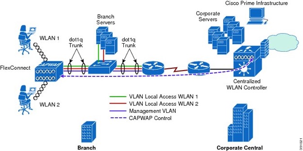
On a high-level, the Cisco WLC solution provides central management for all the APs in the network, including wireless settings such as channels, power budget, interference threshold, user authentication, etc… This is implemented by loading a lightweight version of the AireOS software on the APs, which connects back to the WLC using the Control and Provisioning for Wireless Access Points (CAPWAP) protocol. There are different operating modes for the chosen solution in regards to how the APs forward data and control traffic, both with pros and cons; this document will expand on this matter in section 3.5.
The specific devices models are the following:
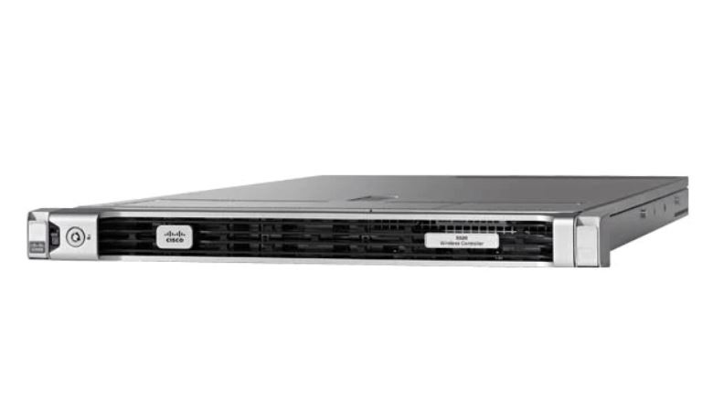
- Cisco Wireless Lan Controller 5520: Main controller, based on a Cisco UCS 220 M4 server modified with a dual SFP+10G NIC and a specific CPU/RAM/HDD setup to support the AireOS software up to 1500 APs.
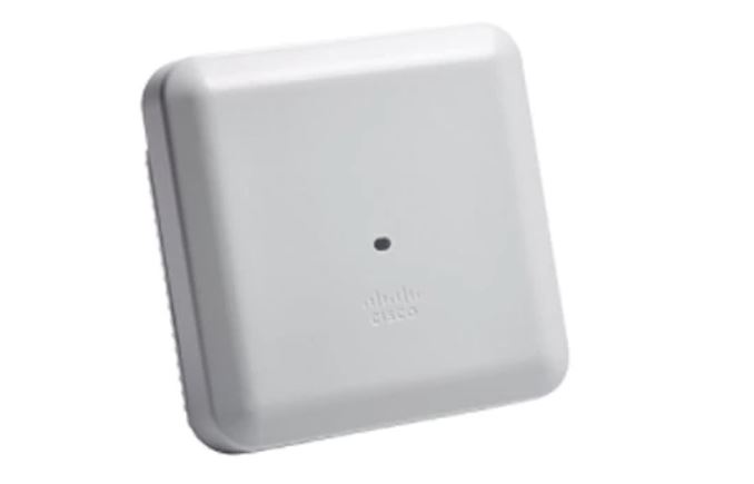
- Cisco Access Point 3802i: Lightweight AP with support for Wi-Fi 4 and 5, N-Base-T, and dual Wi-Fi 5 internal omnidirectional antennas. To be used indoors (e.g. office areas, industrial but enclosed areas, etc..).
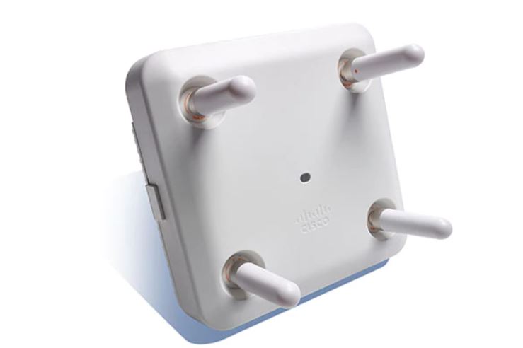
- Cisco Access Point 3802e: Lightweight AP with support for Wi-Fi 4 and 5, N-Base-T, and dual Wi-Fi 5 external omnidirectional antennas. To be used indoors, in areas with increased coverage requirements (e.g. industrial but enclosed areas).
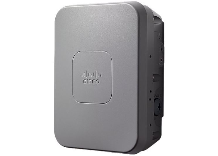
- Cisco Access Point 1562i: Lightweight ruggedized AP with support for Wi-Fi 4 and 5, 1000-Base-T, and internal semi-omnidirectional antennas. To be used outdoors, it includes an SFP+ port for fiber connectivity.
- Cisco Access Point 3702i:* Lightweight AP with support for Wi-Fi 4 and 5 (only wave 1), 1000-Base-T, and internal omnidirectional antennas. To be used indoors (e.g. office areas, industrial but enclosed areas, etc..).
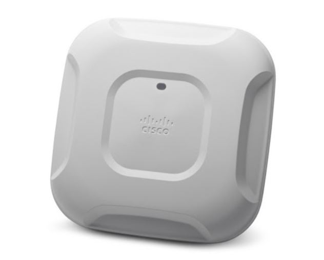
*This model was not part of the original Cisco offering and it was chosen in 2019 as an additional cost-effective alternative for less demanding areas such as the Rubin Observatory summit Villa.
3 Proposed Wireless Architecture
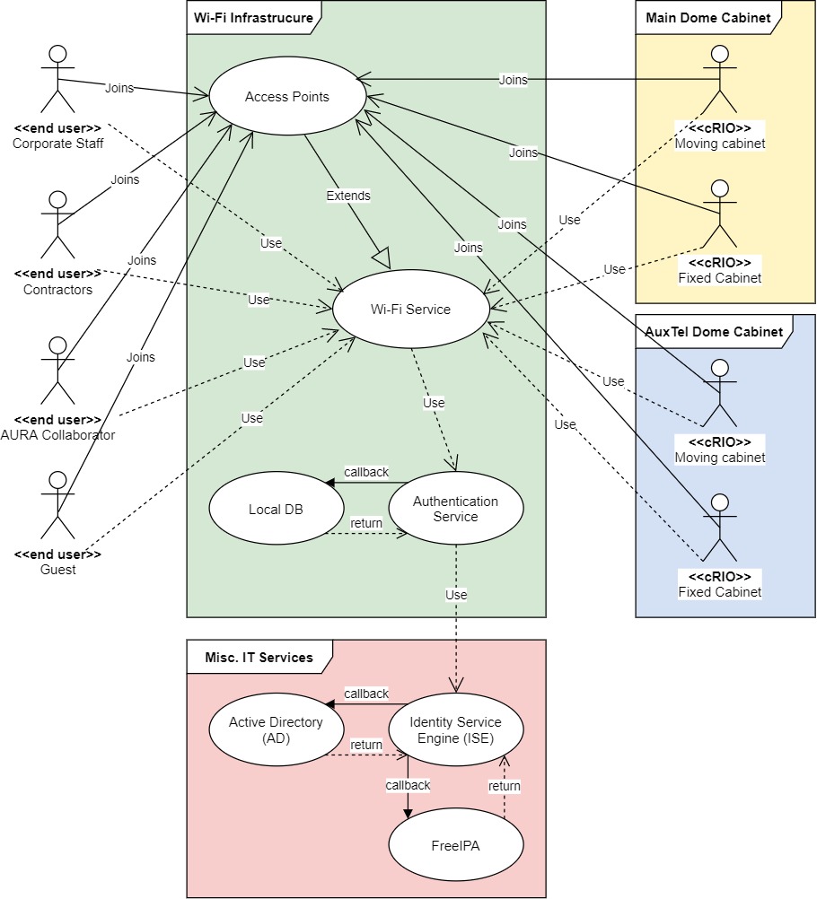
3.1 Logical Design
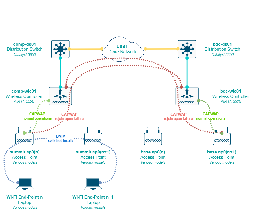
3.2 Physical Design
3.3 Scalability
Scalability is achieved by having a centralized control plane in the WLC itself, being limited only by the hardware capabilities of such device, which in this case is 1500 APs per site, and if we need more than that at any given point we have 2 advisable options:
- Temporarily moving the mission-critical APs to the next site’s WLC (either summit or base) to keep service going (i.e. forcing registration with this controller), and replace the exhausted WLC for a newer model with more hardware capabilities.
- Add an additional WLC in parallel (either physical or virtual, if there are enough capabilities in the local VMware cluster) to the existing ones at any of the sites, and associate the new group of APs to that controller. Using a local switching (flex connect) approach allows us to provide the same level of service at the wireless access layer even of the APs are registered on a different controller.
To allow for the first option, we must always leave at least a 2% of the maximum WLC AP capacity, in this case, we should leave at least 30 AP slots available for such a migration scenario.
Licensing scales well as it’s on-demand, we buy them as we grow. License count depends on the deployment set up in case of redundancy; for controllers with local control-plane redundancy, (i.e. 2 controllers at each site in HA) licenses are in general terms needed only at the primary unit, but for redundancy using controllers in other of the sites, each controller should have enough licenses to support all the AP number across all sites. There is a trade-off in that decision and conclusions are drawn on that matter in section 3.5.
3.4 Design Considerations
- The Wi-Fi coverage must be planned using the least capable, most important (LCMI) device sensitivity as the design driver. Primary coverage should be at -65 dBm, secondary coverage at -67 dBm and -85 dBm is the start of the “don’t care coverage”. Due to the construction components of each building, being concrete a common factor, these requirements may be difficult to be achieved in certain areas, therefore primary coverage is a must but secondary coverage is a “nice to have”.
- For AP’s transmission power, in most scenarios, 11 dBm for Wi-Fi 4 and 17 dBm for Wi-Fi 5 is sufficient with 25dB of SNR. However, we may go over those levels in buildings with a high presence of metal or concrete pillars/walls to satisfy at least the primary coverage requirements.
- The behavior of the Wi-Fi clients depends largely on the antenna type used by the device, the vendor hardware, and especially the drivers used by the vendor. Apple devices are extremely sticky in terms of roaming, their driver implementation doesn’t follow the international recommendations and is therefore not validated properly, which leads to additional tuning in terms of channels and special features to increase the level of experience for users of such devices. Cisco has an entire guide for Apple device’s best practices on WLC controllers which must be implemented at all sites.
- To increase the quality of experience, mostly for sticky clients, lower data rates must be disabled and 12mbps must be the Minimum Basic Rate (MBR), with upper data rates offered as supported, with exception of 18mbps which must also be disabled to avoid issues with older Wi-Fi 5 clients with hardcoded supported data rates (6, 12 and 24mbps specifically). 24mbps can be marked as mandatory as well but it’s not strictly necessary; if offered by the AP, the client will automatically use the 24mbps rate when it gets closer to the AP and start roaming when it gets to the limit coverage of the 12mbps.
- To increase the quality of experience, small cells must be configured, meaning lower transmission power with more AP density for improved air-time and reduced Co-Channel Interference (CCI), which on top of using 12Mbps as the MBR, provides a baseline acceptable service even for Apple devices.
- Band steering doesn’t work properly with any vendor, which has been proved several times by the Wireless Professional Community. Wi-Fi 4 and Wi-Fi 5 should be separated in different SSIDs. All the critical loads (applications) should be using the Wi-Fi 5 SSID as there’s less interference due to the increased channel availability. Interference in Wi-Fi 4 is difficult if not impossible to mitigate in most cases, therefore Wi-Fi 4 should be used only for legacy devices and miscellaneous (i.e. non-mission critical) devices. If there is a need for Wi-Fi 4 SSIDs in a low interference environment, the requirement must be treated with extreme caution, and RF isolation and/or mitigation in that environment must be possible (e.g. containing signal within wide concrete walls).
- A pre-deployment design is necessary using the CAD drawings from the buildings, specifying the type of walls, height of the APs from the ground, its polarities, and transmission power levels. This is done with special software. When this design is done, a site-survey has to be done with an “AP on a stick” technique to crosscheck the results of the AP locations.
- Depending on the building floor plan, APs should be ideally placed inside offices and avoid hallways when possible. Hallways are good spots to fix holes in signal coverage but not to provide primary coverage.
- Once the APs are installed, a post-deployment site survey must be repeated, as changes of materials in the building construction, furniture, some special lights, and wiring can affect the signal strength.
- Considering the building layout and some materials inherent composition, shafts, restrooms (unless explicitly required), staircases, and small storage rooms are considered a “don’t care” area in terms of coverage.
- AP location and power levels should not be set up with the idea of the signal escaping the building (e.g. through glass planes, for instance) as this not only provides a poor/weaker signal but leads to unpredictable behaviors depending on the client device. If coverage is needed outside the building, then the use of additional outdoor, directional or omnidirectional, APs is advisable.
3.5 Redundancy and High-Availability
Given the requirements, the chosen solution and the design considerations, a combination of redundant controllers, one per-site, plus the use of APs in flex connect mode with local switching is the best approach for our use-case. High-availability can be implemented at each site with a standby controller (directly connected via the redundancy port) that takes over the control plane in case a failure of the main controller, but it is not effective across sites due to its physical dependency on the cable connecting the controllers, therefore, implementing high-availability at each site doubles the amount of hardware needed (2 controllers per-site) while providing marginal benefit in terms of service continuity. A summary of both approach as follows:
- Redundant controllers with APs in flex connect mode: Each AP registers with the controller at its local site. Switching is done locally and control plane protocols are managed by the controller. In case of failure, after the keepalive threshold is breached, the AP registers with the controller at the other site (i.e. mounts a CAPWAP tunnel with the controller). During the failure, already authenticated users keep connectivity until they are dissociated from the AP due to a timeout of when trying to roam. For WPA2 PSK authentication can still happen without the controller, only WPA2 Enterprise SSIDs would lose the ability to authenticate.
- Cost factors: Doubles the license need per controller, each site should be able to support the full AP load of each other in case of a failure, but only 2 controllers are needed and no dependency on L2 or physically adjacent connections is needed.
- Functional factors: Due to local switching happening at each AP, mission-critical devices remain connected while the APs rejoin the new controller. Connectivity is never lost for authenticated users. The controllers at each site must have a baseline common configuration for rejoining to work (e.g. if an SSID exists at the summit, it also has to exist at the base, even if not used in that site).
- HA controllers with APs in flex connect mode: Same as the first option, the APs register with its local controller but in case of failure, the control plane is handed over to the standby controller, physically located at the same site. Authentication is never lost, the CAPWAP tunnels are maintained but this only considers a site-specific failure. If the redundant port cable is disconnected between the controllers or in case of a dual failure scenario, the APs would still need to register with the controller at the other side, in which case the local switching maintains connectivity for already authenticated users while the AP rejoins.
- Cost factors: If HA is only needed per-site, a 1:1 ratio of AP to licenses is required, but if we want to cover dual failure scenarios, still doubling the AP licenses to support the AP load of the other site is necessary, on top of doubling the number of controllers due to the HA requirements (2 controllers per site).
- Functional factors: Local switching is common to a redundant and HA approach, but in HA mode the control plane is not lost for site-specific failures.
Considering the points mentioned above, implementing HA for the best case scenario double the cost of hardware and licensing, while adding little benefit to site-specific failures, which can be mitigated with the APs in flex connect mode with local switching for mission-critical devices. Given the use-case, the redundant controller approach can scale to an HA approach easily in the future.
3.6 Security
The chosen solution provides a broad range of security options, including direct integration with services like Cisco Umbrella, Cisco ISE and ACS, external Radius servers, local DB users, mac address authentication, etc… but for the sake of simplicity and to cover the baseline requirements, these are the security features to be considered for a low-level design.
Wireless access should be segmented per type of user: corporate users (including science collaborations), contractors, AURA collaborators (specifically at the summit), and guests.
- Corporate SSIDs should authenticate corporate users using WPA2 Enterprise (802.1x) with their domain credentials. An external NAC service such as Cisco ISE must discern if the device is personal or project-funded, and authenticate it into the right network, following the least privilege principle.
- Contractors SSIDs should authenticate with a combination of WPA2 PSK and mac address filtering, local to the controller, or using an external NAC service such as Cisco ISE. This SSID must be behind a protected network with restricted access to the internet only and not to the internal network by default, with the exception of public DMZ services. Contractors must fill up a form (which includes an AUP) before accessing the network, as they may also request access to small portions of the internal network.
- AURA collaborators SSIDs can authenticate either with the same principles as the contractors network or use WPA2 Enterprise, given than other AURA projects provide accessibility to their Radius services. The difference is that AURA collaborators are placed in a network allowing internet and AURA intranet access, with tight control on access to the project’s internal network.
- Guest SSIDs can be open and use a captive portal with fixed usernames and passwords, which can be local to the controller or available in an external NAC service such as Cisco ISE. Self-service portals for auto-registration are also acceptable, given the approval from the project CSO.
3.7 Monitoring
The monitoring is done initially by the controller itself with the AireOS provided features for notifications, warnings, and SNMP-traps. An SNMP service can also query the controllers using the Cisco-provided MIBs for basic hardware parameters such as CPU, RAM, and HDD load, plus additional parameters such as per-AP client load, coverage holes, interference, etc… depending on the level of granularity needed by the System Administrator in conjunction with the Network Engineer.
Logging is done via Syslog at debugging level to the local Syslog collector of the site and alerts may be configured for specific messages such as AP downs, hardware issues, etc… as a backup of the SNMP monitoring.
The APs don’t need to be monitored directly via SNMP or send Syslog to the collector as that’s managed by the controller, but simple ICMP monitoring to its management interface is advisable, as it tends to be faster than SNMP or even Syslog to trigger an alert.
Custom scripting using SSH and the AireOS CLI is also acceptable given the use-case, as well as the use of software abstraction layers that can query the controllers via CLI and present that information to other services or databases.
3.8 Management
Several types of management are available for the chose solution but the following must be implemented as the baseline:
- In-band management access to the controller must be based on TACACS+ provided by a Cisco ISE cluster, synchronized with the local domain controller of the site, and implementing differentiated levels of access. For IT network administrators, the regular domain account shall provide read-only access and the admin domain account shall provide full access to the controller.
- Out-Of-Band (OOB) management is done via the service port, which is placed in a different and more protected network than in-band management.
- IPMI/BMC access is provided by the onboard Cisco CIMC hardware, also placed in a different and more protected network than in-band management. It may or not be in the same as the OOB management segment.
- The APs must be pushed with a specific local account for direct SSH access if needed. It’s advisable that this account is local to the controller and not a domain account, to avoid lock-down scenarios when multiple network failures occur (e.g. the Radius servers not being reachable over the network).
4 Appendix
4.1 Terminology and acronyms
| Term | Meaning |
|---|---|
| ACS | Access Control Service |
| AD | Active Directory |
| AP | Access Point |
| AURA | Associated Universities for Research in Astronomy |
| CAPWAP | Control and Provisioning for Wireless Access Point |
| CCI | Co-Channel Interference |
| CIMC | Cisco Integrated Management Controller |
| CISS | Computing Information Services South |
| CLI | Command-line interface |
| CTIO | Cerro Tololo Inter-American Observatory |
| DB | Database |
| HA | High Availability |
| HDD | Hard-Drive Disk |
| HLD | High-Level Design |
| ICD | Interface Control Document |
| IEEE | Institute of Electrical and Electronics Engineers |
| ISE | Identity Service Engine |
| IT | Information Technology |
| LCMI | Least capable, most important |
| LDAP | Lightweight Directory Access Protocol |
| LLD | Low-Level Design |
| LSST | Large Synoptic Survey Telescope |
| MBR | Minimum Basic Rate |
| MIB | Management Information Base |
| NIC | Network Interface Card |
| NOAO | National Optical Astronomy Observatory |
| OOB | Out of band |
| PSK | Pre-Shared Key |
| RADIUS | Remote Authentication Dial-In User Service |
| RRM | Radio resource management |
| RSSI | Received Signal Strength Indicator |
| SNMP | Simple Network Management Protocol |
| SNR | Signal to noise ratio |
| SSH | Secure Shell |
| SSID | Service Set Identifier |
| TACACS | Terminal Access Controller Access Control System |
| VLAN | Virtual local area network |
| WLC | Wireless Lan Controller |
| WPA | Wi-Fi Protected Access |